
ViewMold Co Ltd is an ISO 9001:2000 certified plastic injection molds company that supplies
plastic injection molds
plastic injection molds design
plastic injection molds manufacturing of high quality,plastic injection molding...
We are Proud to bring to you the quality and speed you would expect from Viewmold plastic injection molds. We believe we will be your supplier of choice. Just give Viewmold a
email or
submit a quote online.
Our team of quote specialists is the most responsive and the most hands on.
BOSTON?/span> IS YOUR BEST SOURCE . . .
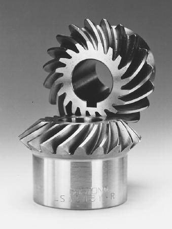
MITER AND BEVEL GEARS
90?Intersecting Shaft Applications
Coniflex Tooth Form for Increased Life and
Smoother, Quieter Operation
Spiral Miter and Bevel for Higher Speed, Greater
Torque Load, and Quieter Operating Applications
Miter Gears for 1:1 Ratio Applications
Bevel Gears for 1.5:1 to 6:1 Ratio Applications
Soft Bores for Customized Alterations

Selections from Stock
Straight Miter Gears
CNylon (48 DP -16 DP)
CBrass (48 DP -24 Dp)
CSteel (48 DP -4 DP)
CIron (8 DP -4 DP)
Spiral Miter Gears (35?Spiral Angle)
CSteel (18 DP -5 DP)
Straight Bevel Gears
CBrass (48 DP -24 DP)
Steel (20 DP -6 DP)
CIron (16 DP -4 DP)
Spiral Bevel Gears (35?Spiral Angle)
CSteel (30 DP -8 DP)
Diametral Pitch -48 DP to 4 DP)
Pitch Diameter -0.250" to 9.000
20?Pressure Angle
Hardened or Unhardened Teeth (Steel)
Made in Accordance with AGMA
Specifications for the Basic Tooth Form
Boston miter and bevel gears are designed for transmission of motion and
power between intersecting shafts positioned at a right angle. Straight tooth
miter and bevel gears are cut with a generated tooth form having a localized
lengthwise tooth bearings known as the ?Coniflex tooth form. The superiority
of these gears over straight bevels with full length tooth bearing lies in the control of tooth contact. The localization of contact permits minor adjustment of
the gears in assembly and allows for some displacement due to deflection
under operating loads, without concentration of the load on the end of the
tooth. This results in increased life and quieter operation.
Spiral tooth form miter and bevel gears are suited for higher speed and larger
torque applications.
Boston stock miter and bevel gears are designed for transmission of power
and/or motion between intersecting shafts at a right angle (90?). Miter gears ar
a special type of bevel gear designed to operate as pairs being identical in number of teeth and pitch (1 to 1 ratio only). Other Boston stock bevel gear sets are available with ratios from 1-1/2:1 to 6:1.
All Boston standard stock bevels and miters are manufactured with a 20?pressure angle. These bevel gears are made in accordance with AGMA specifications for a long and short addendum system for gears and pinions, which serves
to reduce the amount of pinion tooth undercut and to nearly equalize the strength
and durability of the gear and pinion. Boston straight tooth bevel and miter gears have generated teeth with ?Coniflex
tooth form, unless otherwise specified.
INTERCHANGE
Stock miter and bevel gears having identical diametral pitch, number of teeth
and mounting distance (and spiral angle for spiral bevels) are interchangeable.
SPIRAL VS. STRAIGHT TOOTH
Boston standard stock straight bevel gears can be used for all applications
requiring transmission of power and motion between intersecting shafts. Boston
standard stock spiral bevel gears have an overlapping tooth action which results
in a smoother gear action, lower noise, and higher load capacity than a straight
bevel of equal size.
SELECTION PROCEDURE
Approximate horsepower ratings for selected sizes (number of
teeth) at various operating speeds (RPM) are given for Boston
standard stock Bevel and Miter gears.
For straight tooth Miter gears, refer to Pages 68, 69.
For straight tooth Bevel gears, refer to Page 70.
For spiral tooth Miter gears, refer to Page 71.
For spiral tooth Bevel gears, refer to Page 71.
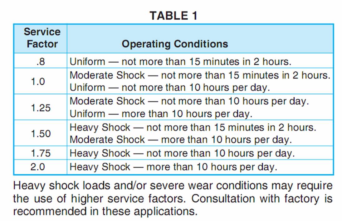
All ratings are based on normal operating conditions, that is:
properly mounted and lubricated, carrying a smooth load for
not more than 10 hours (Service Factor = 1.0). Refer toTable 1
for service factors in other service conditions.
1. Determine service factor.
a.Using Application Classification Chart I, pages 152(R)C15 determine service factor or
b.With knowledge of operating conditions and load classification, select service factor from Table 1.
2. Determine Design Horsepower.
Design HP = Application Load x Service Factor (Table 1)
3.Select a gear set with horsepower capacity equal to (or
greater than) design horsepower determined in Step 2.